

Roll Cutter User Guide
Customer Service
The roll cutter includes several mechanical and software adjustments to accommodate a wide variety of materials, including paper and film. If not properly adjusted, you may experience issues, but if the Troubleshooting section does not solve your issue, our customer support team is happy to help. Contact staff@krexil.com or call 551-600-1400 M-F 9am-5pm EST. Please provide your menu settings, material type, thickness, width, cut length and roll diameter. Krexil welcomes your feedback and requests for customized versions.
Important Safety Guidelines
- Read all instructions before using.
- Do not use the device for anything other than the intended use.
- Place the device on a flat, firm, stable surface.
- Disconnect power before making any adjustments or changes.
- Keep the device out of reach of children.
- This device is not intended for use by persons with reduced physical, sensory or mental capabilities or lack of experience, unless supervised by a person responsible for their safety.
- See Replacing Blade when installing or changing the cutting blade.
- Do not operate while under the influence of drugs, alcohol, or medication that may affect your ability to use the tool.
- Keep hands, hair, etc. away from moving parts. Models with 48" width or more have stronger feed motors.
- Print and save these safety instructions.
Avoid Damage
- Stop tightening screws in plastic when you feel increasing resistance.
- Do not bend the 1/2 x 1/16" metal hold-down strips - they have one or more bends that are required for proper function.
- Never unplug or plug in motors with the power cord connected — this can damage the motor driver circuit.
- When manually moving the carriage, do so gently to prevent the motor from generating back current into the driver. Similarly, do not pull media through the pinch rollers quickly.
Console buttons
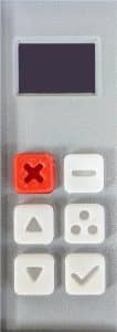
For part names used in these instructions, see Roll Cutter Item Names.
Console commands
| Function | Menu | Submenu | Tips |
|---|---|---|---|
| Set length of cut | Length | ||
| Set quantity of sheets | Count | 1 to 32,000. | |
| Jog material | Jog | Press [↑] to retract material or [↓] to advance. Helpful when threading a new roll or troubleshooting. | |
| Set delay between each sheet | Speed | Delay | Helps set a steady production pace. |
| Set speed or acceleration | Speed | XSpeed, XAccel, YSpeed, YAccel | Use low values when troubleshooting. Too high values can result in slipping, stalling, or length variation. |
| Set sensor type | Sensor | Type | See the Roll Cutter Accessories Guide for sensor setup details. |
| Set cut width | Settings | Width | Use a width less than the roll width to cut strips that stay attached (e.g. for void fill). |
| Adjust material length accuracy | Settings | Adjust | See steps below. |
| Set sheet eject | Settings | Eject | Feeds material (mm) after the cut to help eject sheets from the hold-down strip. |
| Set retraction | Settings | Retract | Retract material (mm) before the return trip to avoid re-cutting. |
| Set unit of measure | Settings | Unit | Inch, 0.1 inch, mm, cm. |
| Restore factory defaults | Settings | Fact Rst | Record settings, press [✓], then restore needed settings. |
| Show cut count | Settings | Cuts | Resets with Fact Rst. |
| Set gear ratio | Hardware | Gear | Set 1 for ~2 inch feed motors; set 5 for ~5 inch feed motors. |
| Set brightness | Hardware | Bright | Select between 1 and 10. Also see Sleep setting. |
| Set sleep | Hardware | Sleep | Set idle time before the display turns off (wake via any keypress). |
| Set motor direction | Hardware | XDir, YDir | If convenient, instead remove power and reverse the motor connector. Note: the software-only fix is erased by a factory reset. |
| Set microsteps | Hardware | XMicro, YMicro | For Tech Support. |
| Set motor pulley | Hardware | Pulley | For Tech Support. |
| Use test menu | Test | For Tech Support. |
Note that settings made above are auto-saved after 5 seconds at the main menu.
Adjust material length accuracy
Adjust material length accuracy
If the actual length of a sheet differs from the length you enter, follow these steps and see Troubleshooting | Length is not accurate or changes over time:
For orders shipped after 7/23/25
- Set Hardware | Gear to 1 (not 2) for feed motors ~2 inches long or 5 for feed motors ~5 inches long. If you changed the value you might not need the steps below.
- Set Length = 0 and press [✓] to make a cut. This trims the current leading edge before calibration.
- Set Count = 2.
- Set Length to the DESIRED length, such as 10 inches or your specific length.
- Press [✓] to cut.
- Measure the ACTUAL length of the second sheet; the first sheet may be affected by material slack.
- Open Settings | Adjust and note the TUNING value.
- Compute TUNING × ACTUAL / DESIRED and enter that value. Or use the calculator below.
- Press [✓] twice.
- Verify that the length of the second sheet is sufficiently accurate. If not, repeat the process.
- Open Settings | Save and press [✓]. (Orders shipped after 7/25/25 auto save.)
Length calibration calculator
For orders shipped 7/10/25 to 7/23/25
- Note any changes you made to any settings (speed, accel, units, etc).
- Open Settings | FactRst and press [>].
- Set Length = 0 and do a cut to trim the current leading edge before calibration.
- Set Length to 10 inches or your specific length and press [>] to cut.
- Measure the actual length.
- Open Settings | Adjust and press [>].
- Compute ((programmed length X 2) – actual length) X 10.
- Enter the computed value.
- Press [>] three times.
- Verify that the length is sufficiently accurate.
- Restore any settings from step 1.
(Note that changing YSpeed or YAccel can affect this adjustment.)
For orders shipped before 7/9/25
- Set Length = 0 and do a cut to trim the current leading edge before calibration.
Set Length to 10 inches or your specific length and press [>] to cut.
Measure the actual length.
Open Settings | Adjust and press [✔].
Set Settings | Adjust = 5000 (100 for orders shipped before 12/18/24).
Press [✔] to cut to the indicated length.
Measure the cut sheet length.
Multiply the step 5 value times the step 7 value and divide by the step 2 value.
Set Settings | Adjust to the value from step 8.
Open Settings | Save and press [✔].
Enter the value from step 2 and do a cut again to verify that the length is sufficiently accurate.
If you are getting accurate lengths most of the time but with sporadic deviations, do the following test. Remove the roll; set length to 10 inches, set count to ~20, width to 0, Go. Listen to the sound of the drive/O-ring bar. If you hear a thump sound at random times you might need to update your firmware – contact support.
Changing material rolls
How to change rolls
- Safely remove the used roll with its roll support bar from the machine and place it on a table.
- Remove the roll clamp at the right end of the roll.
- Remove the roll support bar from the roll.
- With a ruler, set the left roll clamp position per the diagram to 3.5″ for 12-24″ models or 4.5″ for larger models and tighten the screw. If your model is substantially wider than your roll, place the roll in the center of the roll support bar.
- Standing in front of the machine, place the new roll in front of the machine with the free end of the material on the bottom and pointing towards yourself.
- Insert the roll support bar through the new roll, with the end marked LEFT on the left.
- If you don’t already have roll clamps mounted, mount them and tighten so the roll position can’t drift.
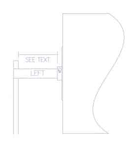
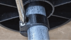
- During initial machine installation or changing to a new roll width, loosen the screw on the right roll clamp, position it at the right end of the roll and retighten the screw – don’t strip the plastic threads but verify that the clamp resists moving.
- Both roll clamps must be outside the roll to constrain roll movement.
- Using two hands carefully mount the roll onto the U shaped support at the rear of the machine. Get help from a second person when appropriate.
- See Material Threading next.
Threading
How to thread the material
If the carriage is not fully left, gently push it there.
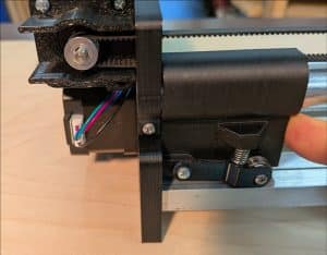
Ensure the material is even at both ends of the roll.
Standard method
- While being CAREFUL NOT TO BEND them, remove the two hold-down strips as follows:
- Gently move the carriage to the far left if not already there.
- For machines shipped after 7/15/25: pull the center of each hold-down strip up about one inch so that it pops out of its recess.
- For machines shipped before 7/15/25: at the right end of the hold-down strips, remove the T-shaped spacer and the retaining clip.
- Lift each hold-down strip up and slide it right a few inches through the small window. Carefully pull the hold-down strip towards yourself an inch to clear the carriage and then to the left and place it on the table.
- Pull out and cut off any wrinkled or creased material with scissors.
- Use a short piece of tape to attach the material to the top of the feed idler bar. Make sure the material is aligned with the roll laterally. Turn the feed idler bar manually (or use the Jog menu) to move the tape backwards, then through the pinch rollers and around to the top of the bar. Remove the tape.
- Locate the rear hold-down strip. If one end has a shallow bend, make sure the bend is on the left and ramping up. Pass the rear hold-down strip a few inches through the small window on the right side and then under the carriage bearing and into the recess in the left panel.
- For machines shipped after 7/15/25: pull the center of the rear hold-down strip up and press the right end down to seat it into the recess in the right panel.
- Mount the front hold-down strip on the front square bar similarly, with the bend on the left and ramping up. Make sure the two hold-down strips cannot slide out of the window on the right – if they can, slide them further left so they can seat down on the right end.
- For machines shipped before 7/15/25, remount the T-shaped spacer and the retaining clip described in the Assembly section.
- Gently push the carriage far left. Manually turn the drive/O-ring bar slowly to retract the material to about the center of the rear square bar and then advance forward to verify that the material passes unobstructed over the front square bar and under the hold-down strips.
How the hold-down strips work: During normal operation, the carriage lifts, or "pops up," the hold-down strips as it returns home after a cut. This creates clearance for the material to feed underneath them. When the next cut starts, the strips press back down to hold the material near the blade. Do not flatten their intentional bends. If a strip does not lift or press back down correctly, verify that both ends are seated in their panel recesses.
New installations:If this is the first use of the machine:
- Advance the material 1-2 inches in front of the aluminum bars. Manually move the carriage slowly to the right and back to far left home to verify a successful cut.
- Set the length to 1 inch to avoid wasting material. Press [✓] to test automated cutting.
- If the rotation of the roll is overshooting after a cut, resulting in drooping material slack between the roll and the cutting area, or you are cutting elastic material:
- Remove the roll support bar with the roll from the machine.
- Remove the screw on one end of the tube and remove the small steel washer. Reverse the bearing so it will be flush with the tube end cap. Screw the bearing back on and verify that the bearing does NOT spin freely. This will create friction to prevent the material from unwanted rotation. If needed, repeat with the other end or consider using a roll brake accessory.
Scissors method
If you prefer, you can thread new rolls without removing the hold-down strips as follows: Cut the material at an angle with scissors. Advance the material to just behind the rear hold-down strip. From the front, slip a business card between the hold-down strips and over or under the material as needed. Gently lift the rear hold-down strip while rotating the feed idler bar to feed the material.
Rotate or replace blade
How to replace blade
For models shipped before 10/1/25, the blade does not normally rotate during cutting so manually rotating it can bring it to a sharper segment.
- Use gloves to protect your hands from the sharp blade.
- Unplug power.
- Remove the front hold-down strip and front square bar.
- Gently slide the carriage to the center.
- Rotate the carriage up for access to the blade.
For machines shipped after 8/19/25
There are two types of blade assemblies – one rotates on a ball bearing; another is fixed.
Remove the front hold-down strip and front square bar.
Use gloves for your protection.
To replace the rotating blade assembly:
Pull the blade assembly out of the snap.
Snap in a new blade assembly or carefully disassemble the unit and replace the blade. When disassembling the unit, hold the nut in a vise such as a low cost small machinist vise, so the blade can be handled with better control.
Remount the blade assembly, front square bar, and hold-down strips.
To install the optional provided fixed blade assembly:
CAUTION: Only qualified individuals should do this procedure as it involves handling the sharp blade multiple times.
- Unplug the cutter.
- Remove the carriage from the machine by reversing the procedure in the Carriage section of the original assembly instructions.
- Using pliers instead of your fingers, carefully pull the rotating blade assembly out of the blade clamp.
- Unbolt the blade clamp from the carriage.
- For safety, hold the nut in a vise. Carefully remove the nut from the rotating blade assembly, followed by the bearing, washers, and blade.
- Insert the provided hex screw through the rectangular 3D-printed holder with the screw head on the side marked with the number.
- Place the washers onto the screw, followed by the blade and then the nut.
- Hold the nut in a vise and tighten the screw with a screwdriver.
- Bolt the fixed blade assembly onto the carriage, then reinstall the carriage by following the original assembly procedure.
- Reinstall the front square bar and hold-down strip, then make a test cut.
After many cuts, if the blade becomes dull, use the provided hex key to rotate the blade a few degrees to a sharp area.
For machines shipped before 8/19/25
To rotate the blade:
- Rotate the blade ~45 deg
- Reassemble.
To replace the blade:
- Unhook the belt from the rear of the carriage.
- Unsnap the carriage from the carriage travel bar.
- Be careful not to lose the springs in the next step.
- Loosen the carriage arm screws one turn and swing them out of the way.
- Remove the screw, insert a new blade and tighten gently without stripping the plastic thread. Make sure the screw head does not obstruct the carriage arm.
- Reassemble – make sure the carriage arms can swing freely by adjusting their screws.
Light-Sensitive Paper and Film
Settings and cutting tips
- Dimmer/display brightness: Open Hardware > Bright and set the display brightness to 1 (minimum).
- Sleep: Open Hardware > Sleep and select a short idle time so the display turns off sooner. Press any key to wake the display.
- Static control: Static buildup can fog or ruin unexposed photographic paper and film. See How to Manage Static When Cutting Photographic Paper and Film for practical control steps.
- Cut-edge quality: Try both the standard rotating blade and the fixed blade method to see which produces the cleaner edge on your material. See How to install the optional provided fixed blade assembly.
Tips
Tips
- To mount the machine on a wall, consider a shelf like the Vevor 12 x 36 in. Be sure that the machine cannot slide off the shelf by adding appropriate constraints.
- Usually one O-ring per foot but not less than two suffice. You can try more to correct feeding issues. Changing the number of O-rings may require recalibrating.
- For unattended cutting, you have a few options for capturing the cut sheets.
- The simplest is to place the machine near the edge of a table and let sheets drop to any lower surface, to be stacked later.
- A corrugated box slightly larger than the sheet size. Remove all but one of the top flaps which gets taped to the edge of the table in front of the cutter so sheets fall into the box.
- Krexil can fabricate a custom metal slide attached to a table edge to collect the output.
Troubleshooting
If you are having any type of issue, please see the helpful Troubleshooting section.
Specifications
See Specifications on the main page.