

Roll Cutter Accessory User Guide
Replacement Blades
Replacement blade details are listed in the General Specifications on the cutter page.
Roll Extension
The roll extension increases roll capacity from 12 inch diameter to 16 inch by moving the roll support tube higher.
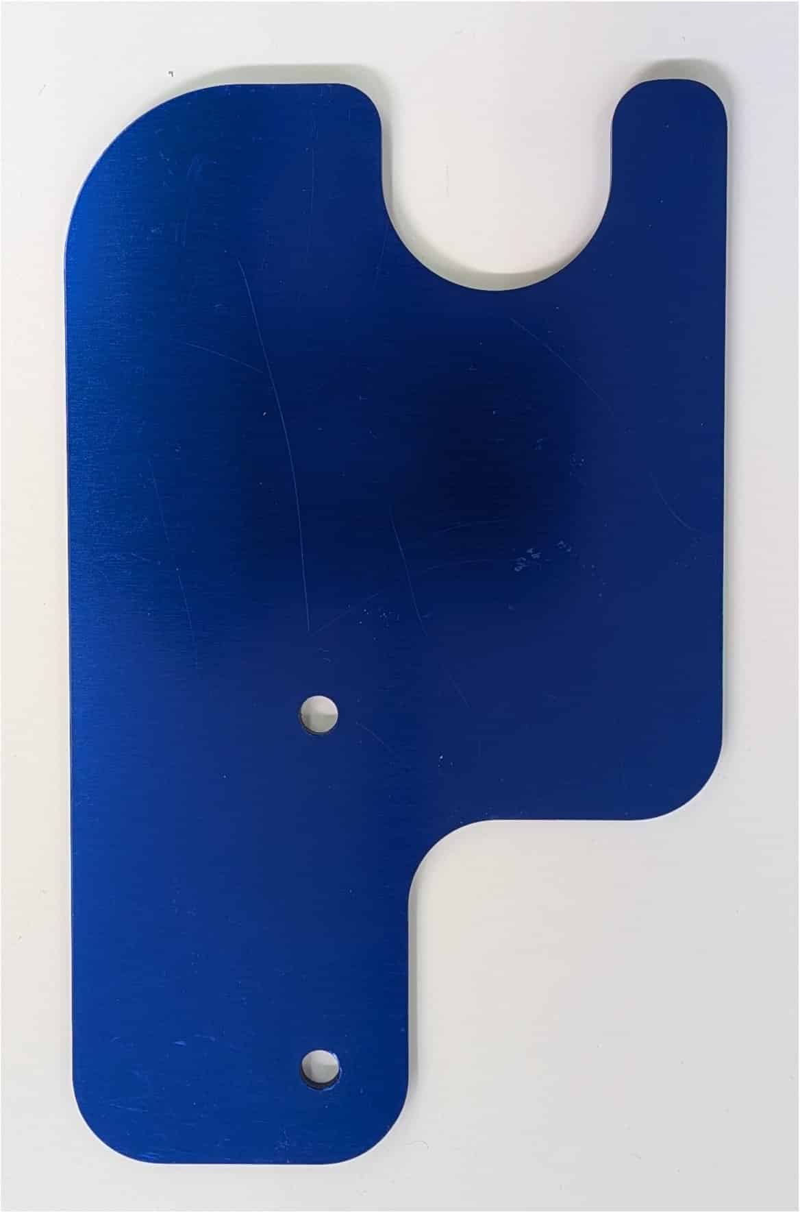
Bolt the two plates to the right side of each panel (as viewed from the front of the machine). Mounting the extension backwards can help minimize the material web getting out of alignment with the roll. To mount backwards, add a couple of washers at each screw as spacers to avoid contact with the nearby screw head.
Carriage Home Sensor
The home sensor verifies that the blade carriage moves properly and reaches the left home position at the expected time. If the carriage is away from home when a cut starts, the cutter searches left at its slowest carriage speed before starting a cycle.
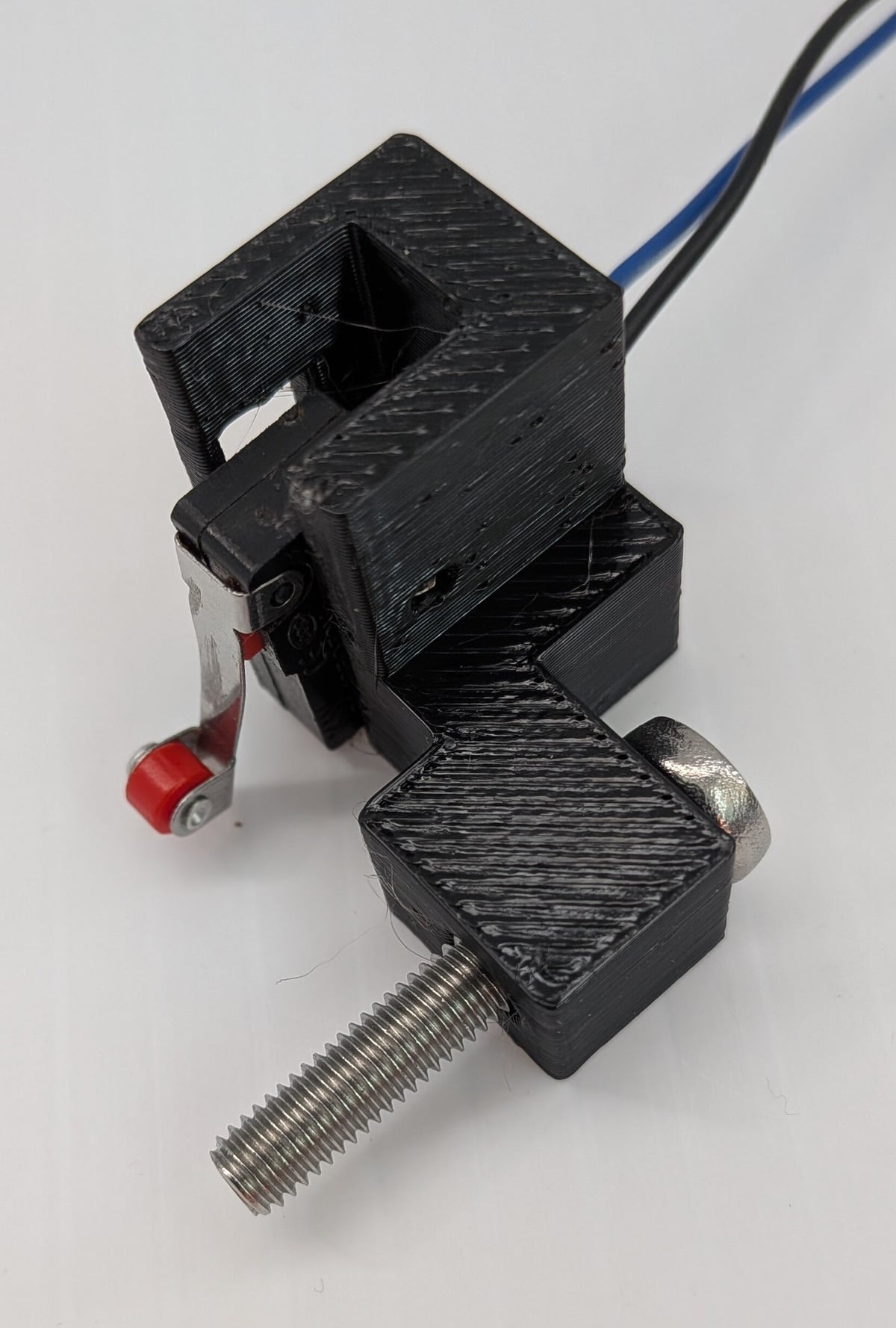
- Disconnect power. Remove the screw holding the left end of the carriage travel tube. Install the sensor assembly with the provided longer screw. Verify that the carriage depresses the switch arm roller as it reaches home.
- Remove the controller cover via 4 screws.
- Connect the switch leads to H6 so that one wire goes to the pin nearest the H6 designator. Reassemble the controller before reconnecting power.
- Open menu Hardware | HOME MM. Use the arrow buttons to set the allowed home-sensor zone from 1 to 20 mm (3 is recommended). A value of 0 disables the home sensor.
- With the carriage at the left home position, verify that the display reads HOME. Move the carriage to the right and verify that it changes to AWAY.
- To test, gently move the carriage to the right about an inch and start a cut. The carriage should first move to the home position and then do the cut.
If the display shows AUX3 USED, another enabled sensor mode is using that input.
If the cutter displays HOME SENSOR ERROR, inspect the switch position, wiring, and carriage movement. After correcting the problem, press any button; the controller will restart.
Just-In-Time Flag Sensor
The JIT-F flag sensor detects when a cut sheet is present or removed, then lets the cutter automatically feed and cut the next sheet after the previous one is taken. This version works with transparent and opaque materials and is generally recommended over the JIT and JIT-S sensors.

If you purchased the sensor after getting your machine: open up the controller; attach the cable so the black or green wire goes to the controller H6 pin (connecting 3 of the 4 pins); reassemble the controller. Attach the cable to the sensor so that the black or green wire connects to the pin marked GND. Clamp the sensor assembly onto the front lower bar, leaning against the square aluminum bar.
To activate the sensor: step to the Sensor menu; click the checkmark button; use the arrow buttons to select JIT-F; manually move the sensor flag and verify that the display toggles accordingly; click [-] to exit the menu. Click the menu button to go to the Count menu, set a quantity of sheets to cut and press the checkmark button. The cutter will feed and cut one sheet, then stop and wait until the sheet is removed before cutting the next.
Just-In-Time Light Sensor
The JIT light sensor detects when an opaque cut sheet is present or removed so the cutter can feed and cut the next sheet after the previous one is taken.
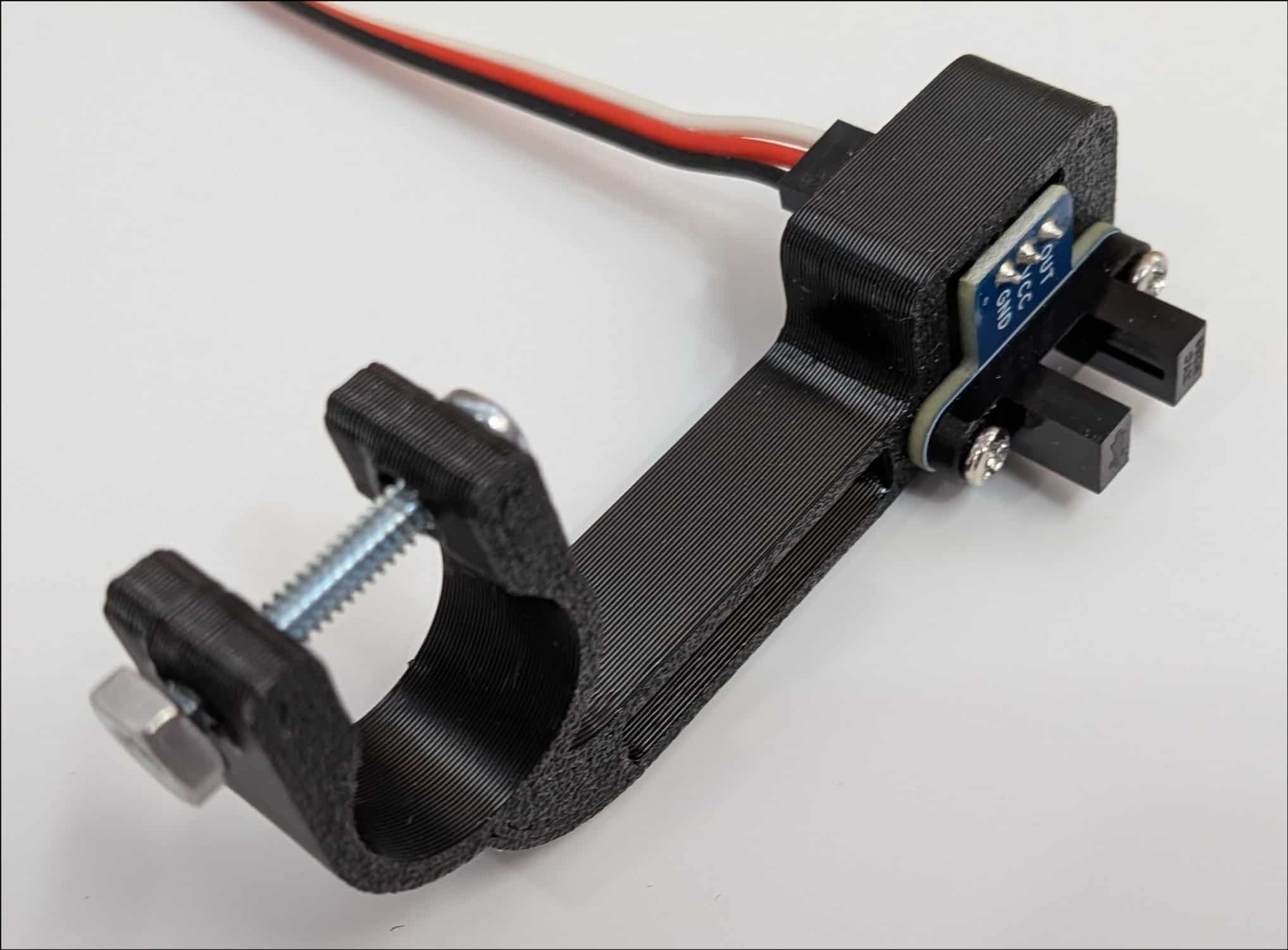
If you purchased the sensor after getting your machine: open up the controller; attach the cable so the black or green wire goes to the controller H6 pin (connecting 3 of the 4 pins); reassemble the controller. Attach the cable to the sensor so that the black or green wire connects to the pin marked GND. Clamp the sensor assembly onto the front lower bar, leaning against the square aluminum bar. Adjust the angle so the carriage can move without touching the sensor and so that material exiting will pass between the two prongs.
To activate the sensor: step to the Sensor menu; click the checkmark button; use the arrow buttons to select JIT; manually insert material between the prongs and verify that the display reflects the sensor status; click [-]. Click the menu button to go to the Count menu, set a quantity of sheets to cut and press the checkmark button. The cutter will feed and cut one sheet, then stop and wait until the sheet is removed before cutting the next.
Just-In-Time Switch Sensor
The JIT-S switch sensor detects sheet removal mechanically and is useful for transparent or translucent films where a light sensor may not be reliable.
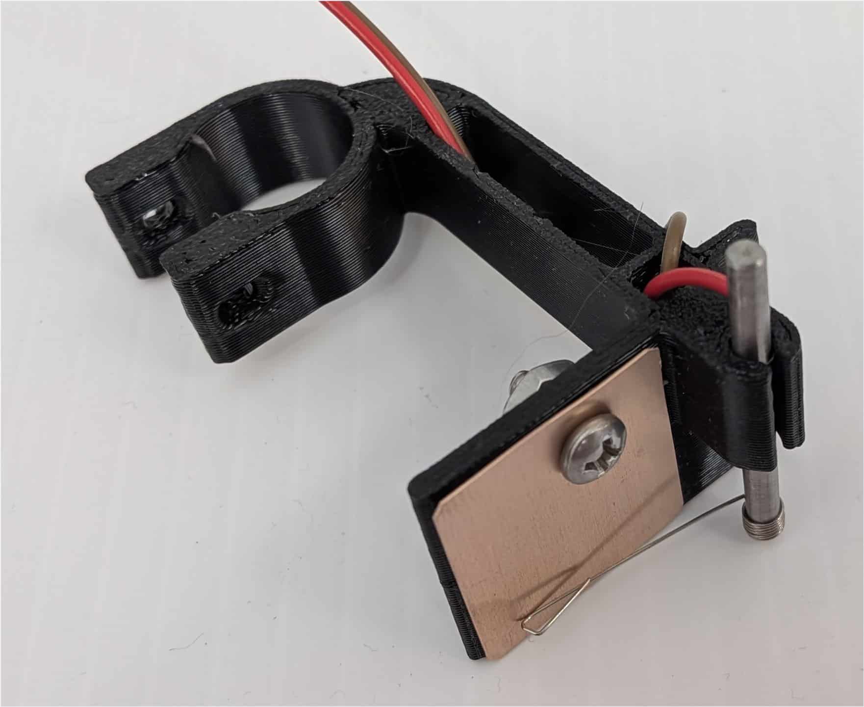
If you purchased the sensor after getting your machine: open up the controller; attach the cable to the two pins nearest H6 (connecting 2 of the 4 pins); reassemble the controller.
If you purchased the sensor with the machine, attach the connector to the two pins on the sensor - polarity does not matter.
Clamp the sensor assembly onto the front lower bar. Using the Jog menu, adjust the sensor position so that material exiting will pass between the metal plate and the spring wire.
To activate the sensor, step to the Sensor menu and use the arrow buttons to select the JIT-S sensor. Place a piece of material under the spring wire to verify that the display changes to "Open".
To test, at the Count menu set a quantity of sheets to cut and press the checkmark button. The cutter will stop after each sheet and resume when the sheet is removed.
To adjust the spring wire, grab the 1/8" steel bar with pliers and turn it so the spring wire gently touches the gold plated surface. Note that a second spring wire attached to one of the screws must contact the steel bar to complete the circuit. You may need to set up support for the output sheet so that the cut sheet stays put.
To turn the sensor off, step to the Sensor menu and use the arrow buttons to select Off.
Mark Sensor
The MARK sensor uses a color sensor to detect printed registration marks on your roll material, allowing the cutter to automatically locate and cut at each mark (for posters, film packaging, brochures, etc.)

If you purchased the sensor:
- after getting your machine: open up the controller; attach the cable so the pin near "H6" connects to the GND pin on the sensor; reassemble the controller.
- with the machine: attach the black, white, or grey wire to the GND pin on the sensor.
Clamp the sensor assembly onto the front lower bar so that the center of the sensor is pointing down where the mark will appear along the left edge of your material.
To avoid wasting material during tuning, consider setting cut Width to 1 inch.
Use the Settings | Unit menu to select a unit of measure - generally, mm or 0.1" is preferred to inch for accurate control near the cut mark.
Step to the Sensor menu; click the checkmark; and use the arrow buttons to select "MARK"; press the checkmark button to enter the Mark settings submenu and use the Menu button to navigate the submenu:
- ON-MRK? — Position the material so the sensor is over a printed mark and the value displayed is lowest (for a dark mark on a light background), then long-press the checkmark button to capture and save the value (typically ~300 for black mark). Or long-press Menu to advance to next menu.
- OFF-MRK? — Position the material over a blank area, then long-press the checkmark button to capture and save the value (typically ~550 for white background). Or long-press Menu to advance to next menu.
- BACK — Distance the feed retracts before the first cut (e.g. 10 for 0.1" unit).
- FORWARD — Distance the cutter advances forward after the first cut if you don't want the mark to appear on the sheet (e.g. 3 for 0.1" unit).
- WINDOW — The length of area near the mark to search for the mark (e.g. 10 for 0.1" unit).
- TIMEOUT — How far the cutter will search for the mark. Typically 1 to 5 inches. (e.g. 30 for 0.1" unit)
- SEARCH — Speed at which the material advances while looking for a mark. Lower is more reliable; higher is faster. Range 1–20. (e.g. 5)
- GAIN — Sensor light sensitivity: 1×, 4×, 16×, or 60×. Start at 1× (lowest). Increase if marks are faint or the contrast between mark and background is low.
After configuring the settings, set a cut quantity at the Count menu and press the checkmark button. The cutter will advance and slow down before getting to the mark. It will then make 1 or 2 cuts near the mark. To turn the sensor off, step to the Sensor menu and use the arrow buttons to select Off.
Note that changes in ambient room lighting can affect the tuning.
Thin Material Support Bar
The purpose of the bar is to reduce the tendency of thin flexible material to sag between the drive bar and the hold-down strips.
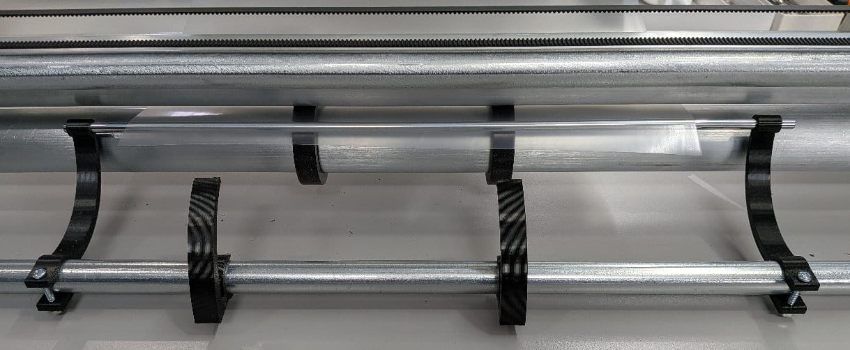
Locate the two clamps with small holes. Slide the provided 6mm smooth rod ends into each clamp. Attach the assembly to the front lower bar so that the rod top surface is level with the square aluminum bars. Gently tighten the clamp screws.
The photo shows the setup from the front of the machine with the aluminum bars removed for clarity.
Gravity Feed Guide
The gravity feed guide directs very flexible material away from the cutter and over the table edge, typically into a catch bin.
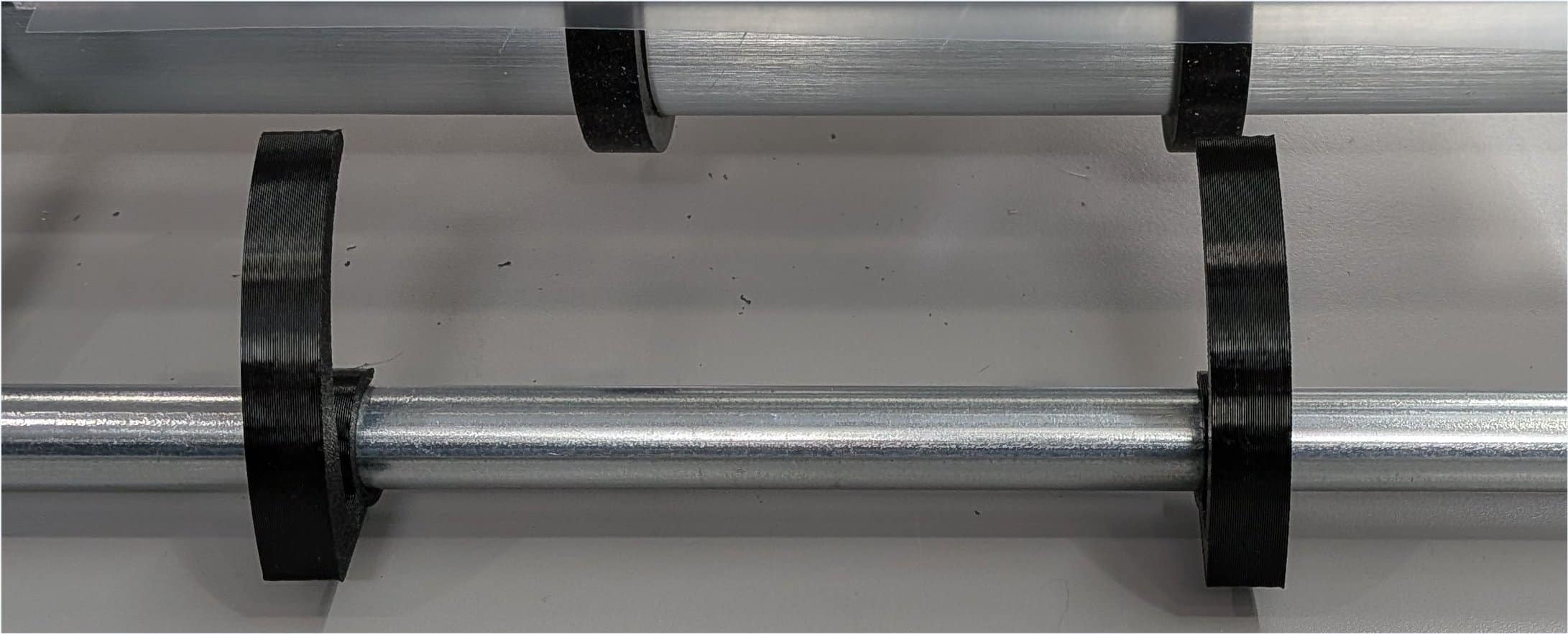
The guide is comprised of two short arc shaped clamps (the inner pair shown above). Attach them onto the front lower bar, about 6" apart with the convex side on top and the free end touching the square aluminum bar (the bar is not shown above).
Brake
The brake applies friction to the material roll so it slows down faster after feeding and reduces roll overshoot.
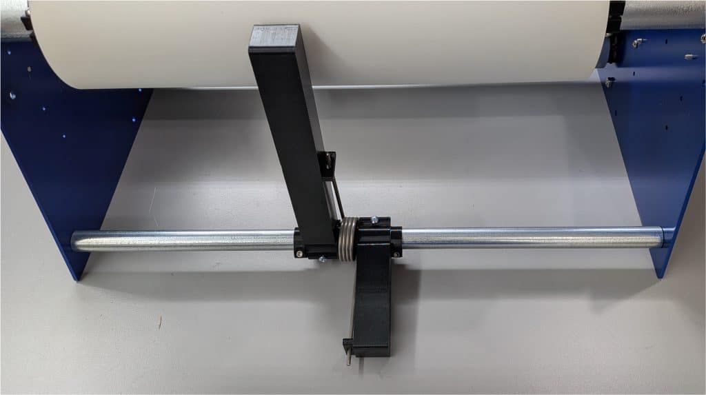
Remove the rear lower fixed bar. Mount all brake components onto the bar as shown in the photo. The round flange goes inside the torsion spring. The two small clamps constrain the position of all components on the fixed bar.
The long bar presses against the material roll to decelerate the roll faster and avoid overshoot. To increase friction, lift the small arm up and tighten the clamp screw to lock the position.
With brake pressure, you should be able to increase acceleration and/or speed. For heavy rolls and/or heavy brake pressure, you might need the larger motor if your model has the smaller stepper - see available accessories.
Large Motor
The large feed motor provides more power for faster material feed with larger or heavier rolls.
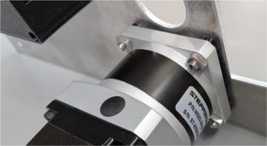
To switch from the small feed motor to the large one: first disconnect power. Detach the wire to the motor by pulling on the connector (not the wires). Unbolt the motor and install the larger one in its place. Remove the 4 screws holding the controller box and the screws holding the PCB. Remove the cable that went to the small motor and replace it with the provided cable with the 4 small windows pointing to the center of the PCB. Make sure all 4 pins are engaged. Reassemble the PCB and the enclosure. Attach the connectors matching up the red wires. Attach power and turn on. Go to menu Hardware | Gear and enter 5. You may need to recalibrate length via Settings | Adjust. If the stepper is feeding material backwards, use the Hardware menu to change direction.
Controller circuit board
The replacement controller circuit board restores the machine controls and motor outputs when the controller electronics need service.
Removal:
- Remove the power cord from the controller.
- Remove the 4 screws on the controller box.
- For 2025 models: remove 2 screws holding the PCB and gently slide the PCB with button panel out of the box.
- For 2026 models: gently slide the controller box away from the chassis and remove the 3 screws holding the PCB to the chassis.
- Disconnect the motor connectors.
- Disconnect the button panel from the PCB.
Replacement:
- Connect the button panel to the new PCB - be careful to align all 12 pins.
- Connect the wire from the upper stepper to the X pins (J4). Make sure the small windows on the connector point towards the center of the PCB and all 4 pins are engaged.
- Connect the wire from the lower stepper to the Y pins (J3) similarly.
- For 2025 models: slide the PCB with the button panel into the box and screw the box to the chassis.
- For 2026 models: screw the PCB to the chassis with the L shaped plastic spacer and screw the enclosure over the PCB to the chassis.
- Do a test cut of one inch to verify the motors are working and moving in the right direction. If not, use the Hardware menu to change the motor direction (or turn off power and reverse the associated connector).