

Roll Cutter Assembly
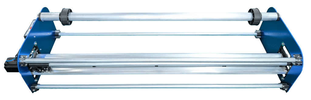
Congratulations on your purchase of the Krexil CNC roll cutter. This device will save you time, material and effort while helping deliver a professional result.
For part names used in these instructions, see Roll Cutter Item Names.
Customer Service
The roll cutter includes several mechanical and software adjustments to accommodate a wide variety of materials, including paper and film. If not properly adjusted, you may experience issues, but if the Troubleshooting section does not solve your issue, our customer support team is happy to help. Contact staff@krexil.com or call 551-600-1400 M-F 9am-5pm EST. Please provide your menu settings, material type, thickness, width, cut length and roll diameter. Krexil welcomes your feedback and requests for customized versions.
Important Safety Guidelines
- Read all instructions before using.
- Do not use the device for anything other than the intended use.
- Place the device on a flat, firm, stable surface.
- Disconnect power before making any adjustments or changes.
- Keep the device out of reach of children.
- This device is not intended for use by persons with reduced physical, sensory or mental capabilities or lack of experience, unless supervised by a person responsible for their safety.
- See Replacing Blade when installing or changing the cutting blade.
- Do not operate while under the influence of drugs, alcohol, or medication that may affect your ability to use the tool.
- Keep hands, hair, etc. away from moving parts. Models with 48" width or more have stronger feed motors.
- Print and save these safety instructions.
Avoid Damage
- Stop tightening screws in plastic when you feel increasing resistance.
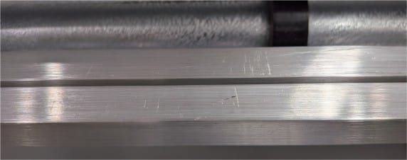
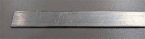
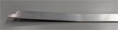
- Do not bend the 1/2 x 1/16" metal hold-down strips - they have one or more bends that are required for proper function.
- Never unplug or plug in motors with the power cord connected — this can damage the motor driver circuit.
- When manually moving the carriage, do so gently to prevent the motor from generating back current into the driver. Similarly, do not pull media through the pinch rollers quickly.
Inspect Shipment
Please check for and promptly report any damage to shipping boxes or shipping tubes. Contact staff@krexil.com with photos of any damage.
You should have:
- (1) Side panel with controller and 1 or 2 stepper motors
- (1) Side panel with labels and side insert
- (6) Round metal bars
- (2) Square metal bars
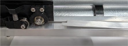
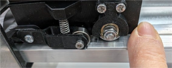
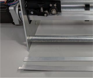
- (2) Hold-down strips (some models have intentional bends and a slight arc)
- (1) Small box containing:
- (1) power pack
- (1) carriage with two carriage arms
- (3 or 4) rubber O-rings
- (1) black timing belt
- (1) small bag of parts
- (1) blade assembly
- (2) roll clamps
- (2) round inserts for 3 inch core rolls
Final cutter assembly
If you received a shipping tube
- Lay the tube flat on a table.
- At each end, rotate the small tabs to release the locking ring from the metal disc.
- Use a flat-head screwdriver to pry the locking ring away from the tube wall and remove the metal disc.
- Caution: Do not bend the hold-down strip — it has a bend at one end and, on larger models, a gentle arc throughout, which is required for proper function.
- Slide the contents out horizontally onto the table.
- Remove bars from the shipping retainers one by one, then remove any tape.
Unpack box(es)
- Open the shipping box or boxes and remove the cutter parts, small parts box, power supply, and hardware.
- Place the side panels, bars, strips, and small parts on a work table.
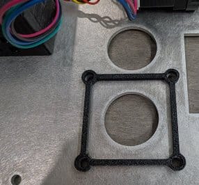
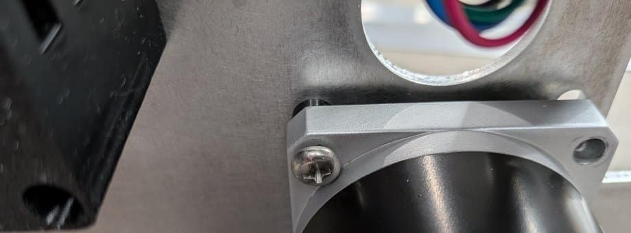
If you received a stepper motor, about 5 inches long, packed separately
Choose text or audio
Use the Play and Pause buttons for spoken guidance so you can focus on the machine with less switching back and forth to the screen.
Frame
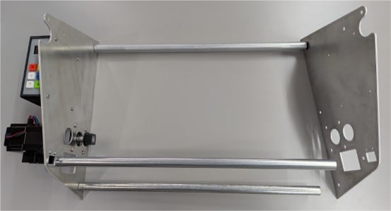
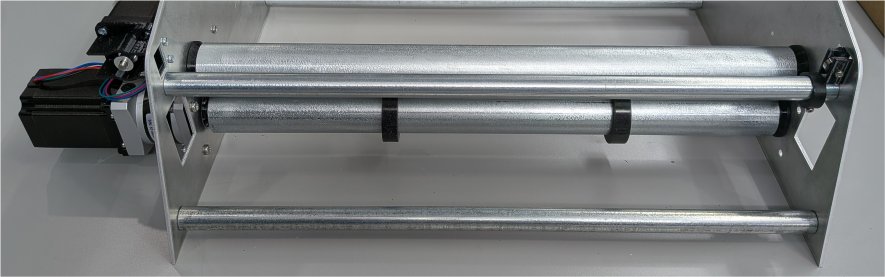
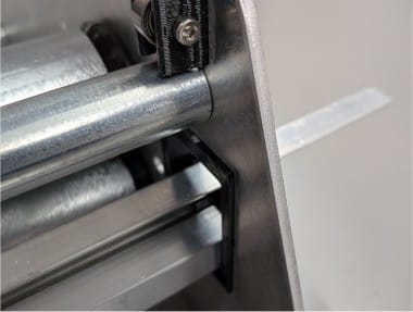
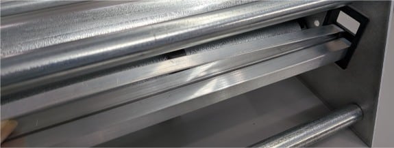
Fit the square or cross-shaped end of the drive/O-ring bar onto the feed motor cam and into the hole in the opposing panel. Screw the front lower narrow bar to the right side panel and then loosen the screw about 5 turns.
Find the feed idler bar, which has free-spinning bearings at both ends, and install it directly above the drive/O-ring bar, locking it in place with a screw through the upper narrow bar. Tighten the three right-side screws.
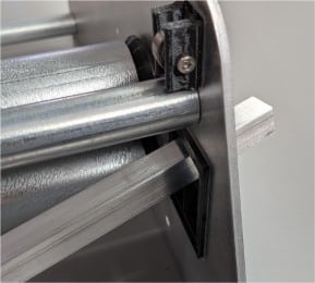
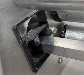
Carriage
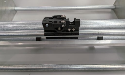

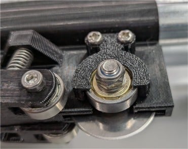
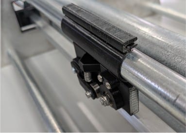
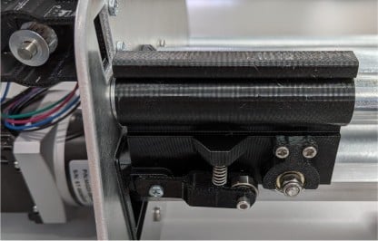
Bars
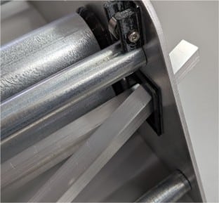
Belt
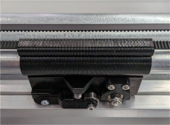
Tension
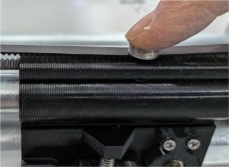
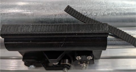
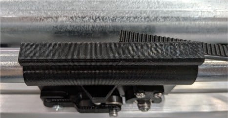
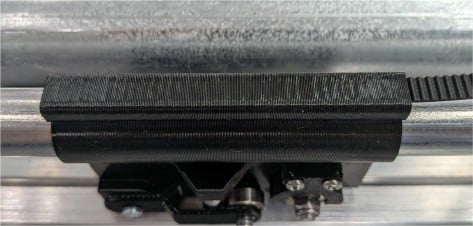
For 12-36 inch models, use the small compression spring as the test tool. Press the spring down against the middle of the belt span. On the 12 inch model, the gap between the belts should close about halfway when the spring is fully compressed. On the 24 inch model, the belts should touch when the spring is fully compressed. On the 36 inch model, the top belt should touch the bottom belt when the spring is half compressed.
For 48 inch and 60 inch models, measure the gap between the two belt runs without the spring. The gap should be 10-12mm for the 48 inch model and 9-11mm for the 60 inch model.
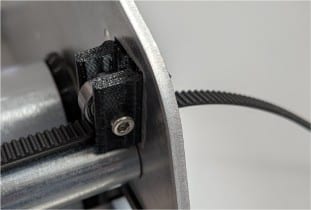
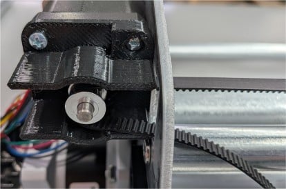
All models: If the tension is out of range, remove one belt end from the carriage and reattach it with more or less belt tension.
Roll
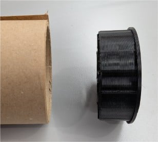
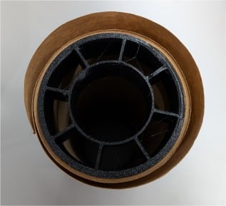
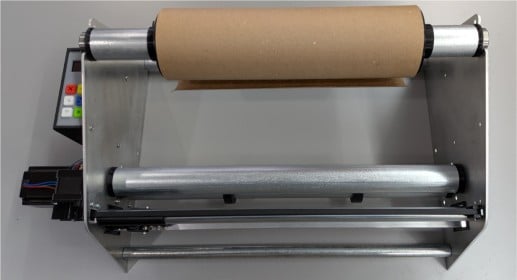
Place the roll support bar onto the frame with the material coming off the bottom towards the front of the machine. For most materials, position the roll so the left edge of the roll is 3.5 inches from the left side panel. For elastic films, center the roll on the roll support bar instead.
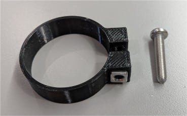
Gently tighten both roll clamps so the roll cannot slide on the roll support bar.
Apply the stick-on label marked "LEFT" to the left end of the roll support bar. This helps install it the same way when changing rolls.
Final
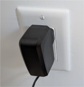
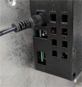
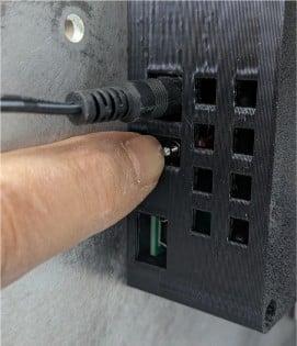
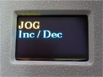
Test and configure
Test motors
- Move to the front of the machine and press the red [X] reset button.
- Verify that the display shows “Length” and you hear a few beeps.
- User the up/down buttons to enter 1.
- Verify that the carriage moves when you press the [✔] button.
- Verify that the material feed bars turn when you press the [✔] button again.
- Verify that the top of the O-rings move towards the front of the machine (nearest the user) when you press [✔] - if reversed use menu Hardware | Y Dir and toggle from 0 to 1.
Configure 48 inch and wider feed motor torque
- Disconnect power before opening the controller.
- Open the controller.
- Turn the small potentiometer on the Y axis driver counterclockwise (CCW) to reduce torque or clockwise (CW) to increase it.
Select inch vs mm etc.
- Navigate to the Unit setting and select your desired unit of measure and press [-] to escape.
Set roll width
- Navigate to the Width setting and enter your roll width.
Adjust carriage clamp
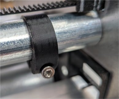
- Spread the small C-clamp and snap on to the carriage travel bar at far right.
- Loosen the C-clamp screw so it slides easily and gently slide it with the carriage to the far left.
- Press [✔] to properly position the c-clamp.
- Without moving the clamp, rotate it to not touch the belt and tighten the screw so it won’t move.
- Press [ ✔] and verify the carriage moves to touch the clamp and back to the feed motor side panel. If you hear a grinding noise go to step 1.
Final assembly complete! See User Guide.
Included accessories
Two small L-shaped brackets with wood screws, machine screws and nuts are provided to attach the machine to a worktable for safety.
A small plastic rectangle is provided to offer an alternate way to hold the blade. For some types of material this method provides a cleaner cut. To use this method, using gloves for safety, disassemble the standard blade assembly and attach the blade to the rectangle with the spacer washers. Remove the clamp from the carriage and replace it with the new assembly. See the detailed fixed blade assembly installation instructions. For unusual materials, Krexil can provide additional variations of the fixed blade holders.
Optional accessories are available for customers who need them.